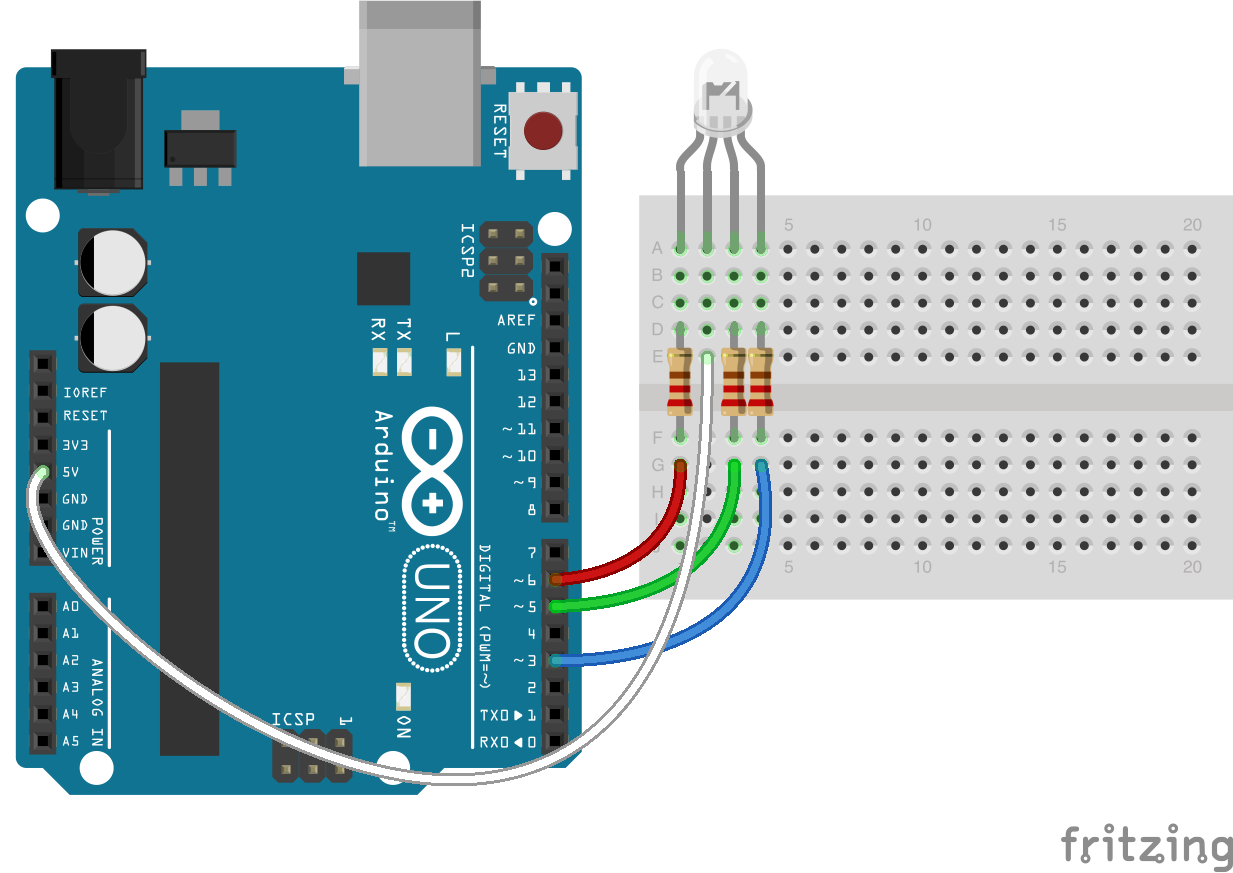

Things used in this project Hardware components Arduino MKR1000 × 1 Power MOSFET N-Channel Might be something similar. You can regulate the brightness of the LEDs via pulse-width modulation. Remotely control your RGB LED strip from your pc. Ever hear of a thing called RGB Red, Green, Blue How about an RGB LED These 5mm units have four pins - Cathode is the longest pin. You will go backwards through the color range in this second for loop. Via mixing the brightness of the different LEDs, you will get different colors. In this for-loop, the 3 LEDs will get different PWM-values Recently, Cytron Technolgies have been integrated many virtual circuits in breadboard view in online tutorials to improve the understanding of users on connections of involved circuits. At the Raspberry Pi, only one Hardware-PWM channel is carried out unrestricted to the GPIO pins, that’s why we have used Software-PWM on this example. Introduction Building a virtual circuit in breadboard view using Fritzing gives a better representation of circuit connections close to the real circuit.
FRITZING RGB LED CODE
This will be shown in the following code example. This module provides a few LEDs – with the overlay of the different brightness levels, you can create different colors. Power LED in three versions: 6pin common anode common cathode Power LED 10W rgb 6pin.fzpz (13.6 KB) Power LED 10W rgb common anode.fzpz (13.3 KB) Power LED 10W rgb common cathode.fzpz (13.3 KB) / V1.1 Fixed the reported fzp and svg bugs. Note: Always use PWM Pins for RGB Led Module
FRITZING RGB LED SERIAL
Then we will setup the serial interface for the three output pins.Figure 2: KY-009 RGB LED Module Arduino Code for KY-009 Module Interface

Then we will initialize the value of the sensor to 0. So in our code, we will assign the output RGB led pins. MAX30102 Oximeter (RCWL-0530) MPXV7002DP Pressure Sensor. The longest pin is the ground pin, so we grounded all of those pins, which is shown through using the yellow wires in the fritzing diagram. The parts are as follows: SparkFun 5-Way Tactile Switch Breakout. The RGB led will only light up when the light detector detects light. After that, we needed to connect the RGB LEDs. Now let us do programming of our Arduino uno. The arduino is programmed to give outputs to trigger the RGB led the moment it receives the input signal from the light detector. When light detector detects light, it’s resistance will decrease so the current will flow through the input pin of the arduino. Then for the output, we will use the PWM outputs, D9, D10 & D11 and to be connected to each output resistors. The input we need for this tutorial is the analog inputs, I will use pin A2 as our input. Then the three pins will be connected to the three output resistors. The supply voltage terminal of our RGB led will be connected to the 5V source. The light sensor will be connected to the 5V output of the arduino and the terminal will be connected to the resistor.


Using the fritzing software, we will create our circuit diagram, prototype using the breadboard and arduino codes.
FRITZING RGB LED HOW TO
The readers will be able to know how to create an automatic lighting system using the RGB LED and to learn the operation of the RGB LED lights controlled by a light sensor.


 0 kommentar(er)
